< Back ×
My Vehicle Change Vehicle
2007 Chevrolet Equinox
< Back to View All
Alignment Kits
- Department
- Prices
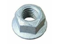
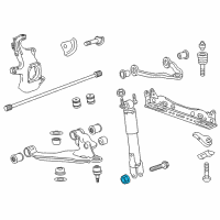
OEM (Genuine) 2007 Chevrolet Equinox U-Bolt Nut
PartNumber: 11516382 Product Specifications
- Notes: 2007-09
- Location: Driver Side; Passenger Side
- Item Dimensions: 4.2 x 3.0 x 0.7 inches
- Item Weight: 0.70 Pounds
- Fitment Type: Direct Replacement
- Replaces: 22123946, 15702050, 15048124, 14013439
- Part Description: 2007 Chevrolet Equinox U-Bolt Nut
Vehicle Fitment- 2007 Chevrolet Equinox | L, LS, LT, LTZ, Premier, Sport | 4 Cyl 2.4 L FLEX, 4 Cyl 2.4 L GAS, 6 Cyl 3.0 L FLEX, 6 Cyl 3.0 L GAS, 6 Cyl 3.4 L GAS, 6 Cyl 3.6 L FLEX, 6 Cyl 3.6 L GAS
$1.14 MSRP:$1.79You Save: $0.65 (37%)
FAQ for Camber and Alignment Kit Repair
Q: How do you adjust the Rear Camber?
A:
You can loosen the upper control arm-to-frame fastener enough to allow movement, rotate the upper control arm-to-frame fastener in the direction necessary to correct the camber measurement, snug the upper control arm-to-frame fastener, without tightening at this time, reinspect the rear camber specifications and adjust as necessary, hold the nut and tighten the upper control arm-to-frame bolt, then repeat the procedure for the other rear wheel.
By Bob
GM Specialist
01/11/2022Q: What's the recommended torque for the link-to-frame fastener bolt?
A:
The recommended torque is 110 N.m (81 lb-ft).
By Bob
GM Specialist
01/11/2022Q: What's the recommended torque for the inner tie rod jam nuts?
A:
The recommended torque is 60 N.m (44 lb-ft).
By Bob
GM Specialist
01/11/2022Q: How do you adjust the Front Toe?
A:
You can position and lock the steering wheel with the vehicle with the wheels in the straight forward position, then loosen both inner tie rod jam nuts, then increase or decrease the toe angle specifications, next tighten the inner tie rod jam nuts, and finally inspect the toe angle to ensure proper adjustment and adjust as necessary.
By Bob
GM Specialist
01/11/2022Q: What should be done before adjusting the Front Camber?
A:
You will need to raise and support the vehicle.
By Bob
GM Specialist
01/11/2022Q: How do you adjust the Rear Toe?
A:
You can loosen the toe link-to-frame fastener enough to allow for movement, rotate the toe link cam nut in the direction necessary to correct the toe angle, snug the upper control arm-to-frame fastener, without tightening at this time, reinspect the rear toe specifications and adjust as necessary, hold the nut and tighten the link-to-frame fastener bolt, then repeat the procedure for the other rear wheel.
By Bob
GM Specialist
01/11/2022Q: How to measure the front and rear alignment angles?
A:
You can install the alignment equipment according to the manufacturer's instructions, then jounce the front and the rear bumpers 3 times before checking the wheel alignment, measure the alignment angles and record the readings, and then adjust alignment angles to vehicle specification, if necessary.
By Bob
GM Specialist
01/11/2022Q: What's the recommended torque for the upper control arm-to-frame bolt?
A:
The recommended torque is 110 N.m (81 lb-ft).
By Bob
GM Specialist
01/11/2022Q: What should I know about the Front Caster adjustment?
A:
The front caster is not adjustable. If the front caster angle is not within specifications, you can inspect for suspension support misalignment or front suspension damage.
By Bob
GM Specialist
01/11/2022Q: What should be noticed when you measure the front and rear alignment angles?
A:
When performing adjustments to vehicles requiring a 4-wheel alignment, you should set the rear wheel alignment angles first to obtain proper front alignment angles.
By Bob
GM Specialist
01/11/2022See more FAQs (6)


